An Architectural diagram can help architects and designers clearly convey design concepts, layouts, and spatial linkages by means of visual representations, therefore simplifying difficult ideas. Particularly in presentations and discussions with stakeholders, customers, or colleagues, their capacity to reduce difficult content into digestible images makes them quite helpful. Architecture diagrams covers topics including their classification, applications, and best practices for producing good designs, this tutorial explores the fundamentals of architectural diagramming like circulation diagrams, concept diagrams and more.
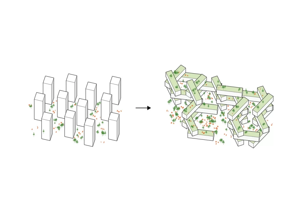
What is an Architecture Diagram?
Architecture diagram for a project is a visual depiction of the fundamental concept, form, and spatial layout found inside a design. Think of architecture diagramming as a way Architects showcase their complicated ideas to clients and engineers. By converting their abstract ideas into a language others can comprehend, they enable architects to realize their vision. The type of diagram could range from basic line drawings to massing diagram, 3D models, depending on the Architect’s style, vision and project.
An architectural diagram mostly serve’s to guide visitors through the logic behind a design and provide a narrative. Architects employ a range of visual techniques to convey the goal, structure, and distinctive features of the project, therefore enabling customers and partners to relate to the concept on a deeper level than they would be able to with just words.
Why Are Architecture Diagrams Important?
The great importance of diagrams in architecture helps in the understanding of structural, spatial linkages even without a degree of technical understanding. A well-made graphic offers an aesthetically pleasing summary that makes a lasting impression, therefore enhancing presentations.
Architectural diagrams are crucial, mostly used in the design process. Using diagrams gives a clear stage for brainstorming and feedback, that generates ideas and investigate viable design solutions with clients and colleagues. Architectural diagramming can also be used late stage to reveal how a design came to be, just as prehistoric cave paintings depicted scenes of early human life. It is very common to find developers and businesses explain how the shape and function have changed using diagrams.
8 Types of Architecture Diagrams
To create diagrams for architecture one must be familiar with the different types and their respective advantages, their purpose and use. Architectural diagrams come in many different forms and, while developing a design, they all have various functions. The following lists 8 of the most important architectural diagram types:
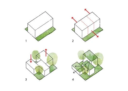
1. Concept Diagram Architecture
Concept diagram architecture, or schematic diagrams, are extremely useful tools and the most used architecture diagram example. By graphically portraying the underlying ideas and concepts, they provide a concise depiction of a project’s core shape and structure. These conceptual diagrams in Architecture usually focus on massing, breaking down the design into its most fundamental components, such as shapes, lines, and volumes. This distillation captures the core of the architectural style while reducing complex ideas.
- Purpose: Aiming for a simplification of the project’s core concept, goal and primary design idea. In architecture, a concept diagram’s primary function is to distill a design’s core parts into a comprehensible visual depiction. Its purpose is to clearly express the project’s fundamental idea, goals, and design ideas. Architects that want to successfully convey their vision to stakeholders, partners, and clients must use these diagrams. Concept diagrams are used to clarify and emphasize the project’s overall aims by breaking down the design into its most fundamental shapes and forms.
- Usage: As the design process moves further, concept architecture diagrams are often examined and updated. The design may evolve while staying true to the original concept thanks to this iterative process. Architects often update these diagrams with new ideas, constraints, or input to keep the project moving forward and meeting its objectives. These diagrams are essential for defining and reiterating the project’s goals because they offer a visual framework for decision-making throughout the design process. In architecture, concept diagrams may also be useful for investigating different design ideas. They facilitate quick and effective idea sharing and can serve as a roadmap to keep the project on course and within its initial objectives.
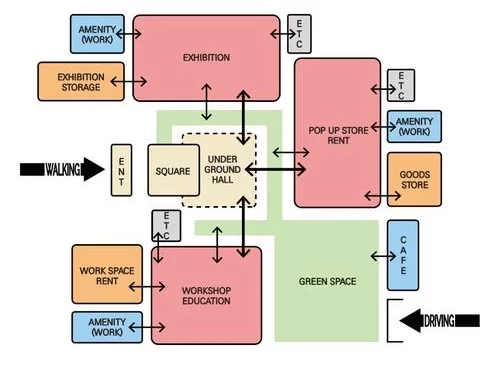
2. Program Diagram Architecture
Program diagrams are the functional components of a project, the programs and functionality. Including reception areas, offices, and bathrooms. They may facilitate preliminary talks by offering a clear depiction of the intended use of each area through the application of colors, iconography, and labeling.
- Purpose: To convey the spatial arrangement of a project’s functions.
- Usage: Used in the early stages of planning to make sure that the layout meets the useful requirements of the project.
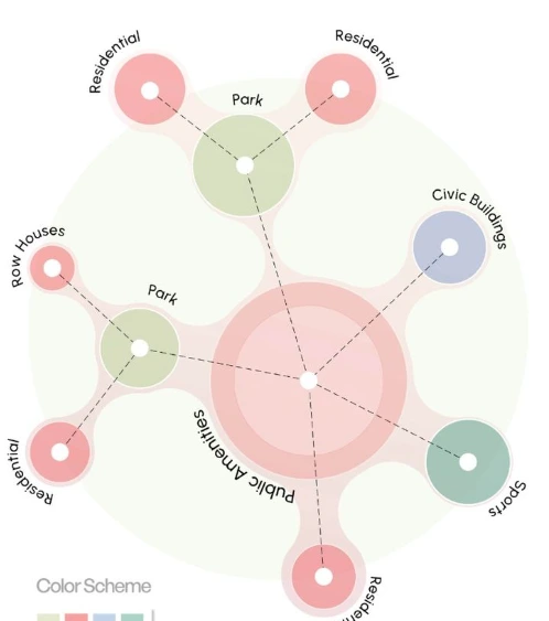
3. Adjacency Diagrams
Adjacency diagrams, which are also known as bubble diagrams or space planning diagrams, show how different areas in a layout are connected to each other. They show how people or things move and interact within the building by showing how places are connected to each other.
- Purpose: To explore the interactions between locations and potential patterns.
- Usage: Useful for planning spatial layouts before final floor plans, therefore maximizing the use of available space.

4. Massing Diagrams
Massing diagrams focus on the overall three-dimensional shape and volume of the structure. They demonstrate the spatial configuration, dimensions, and interconnections of various volumes inside the structure, without emphasizing specific functions or architectural features.
- Purpose: To investigate various configurations and the overall structural integrity of a design.
- Usage: Often used in the early stages of planning to figure out the project’s overall shape and size.
5. Analysis Diagrams
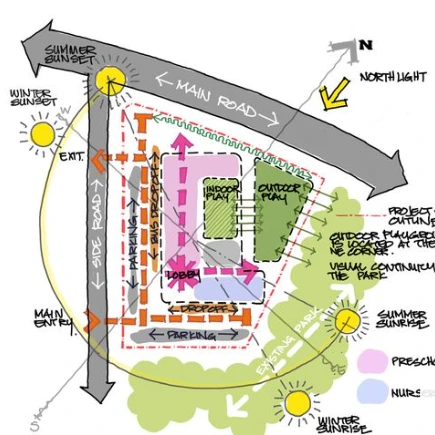
You can tell how a structure will look, how it will be constructed, and where it will go by looking at these diagrams. The two most prevalent kinds of schematics are site diagram architecture and structural diagrams.
- Site Analysis Diagrams: Show external factors like adjacent buildings, topography, and climate.
- Structural Diagrams: Highlight elements like load-bearing walls or facade systems.
- Purpose: So that design choices can be made with an understanding of how to include environmental and social factors.
- Usage: Critical for a building’s aesthetics and functionality in relation to its environment.
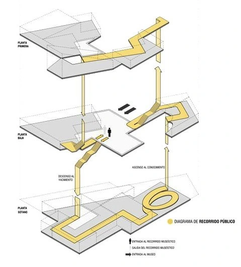
6. Circulation Diagram Architecture
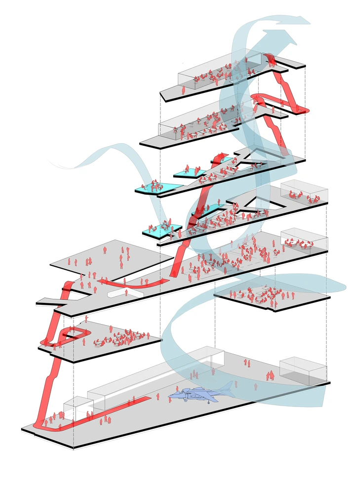
Circulation diagrams in architecture can illustrate the flow of individuals, goods, or processes within a building. The architecture circulation diagram ensures that the circulation is secure and accessible by delineating the pathways, staircases, and emergency exits.
What Are Circulation Diagrams?
A circulation diagram shows how people move about a structure or city. It illustrates how people move logically and efficiently across hallways, rooms, and open spaces. Because they maximize routes for both pedestrian and vehicular traffic, these diagrams are helpful in the construction of buildings.
- Purpose: Outline how users will move and improve the flow of space. Improve spatial flow, efficiency, and user experience. Identify potential bottlenecks or safety concerns. Enhance compliance with accessibility and safety regulations.
- Usage: Used in large projects where excellent mobility affects user satisfaction and safety compliance. Applied in office layouts to optimize employee movement and workflow. Used in sustainable designs to encourage pedestrian movement and minimize reliance on mechanical transportation systems, aligning with LEED certification goals.
Circulation diagrams include color-coded paths, dashed lines, or arrows to indicate the various types of movement. Principal thoroughfares and public access roads are the principal routes for circulation. Restricted-access routes and service corridors make up secondary circulation. Steps, ramps, and elevators are examples of vertical circulation devices.
Circulation diagrams may help architects create more effective, user-friendly structures that increase accessibility, utility, and safety at an early stage of the design process.
7. Process Diagrams
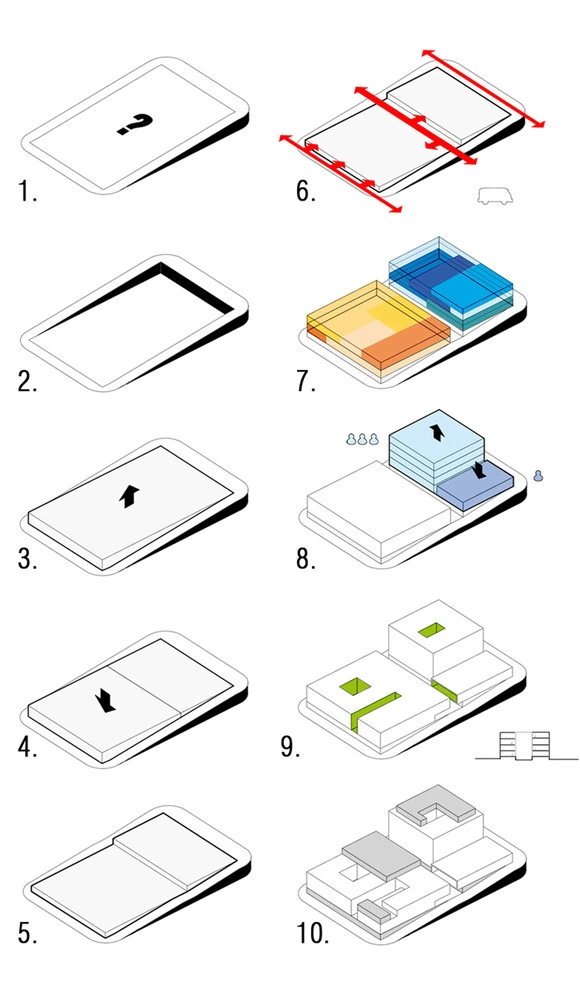
These architectural concept diagrams show the progression of a design, from initial ideas to the final concept. The process architecture diagram is often used to tell the story behind a design, capturing key stages in the development process.
- Purpose: To visually communicate the development and refinement of a design.
- Usage: Helpful for presentations and documentation, allowing stakeholders to follow the design journey from start to finish.

8. Hybrid Diagrams
Hybrid diagrams integrate 2D and 3D representations, digital and hand-drawn elements, or alternative techniques to explain a project comprehensively.
- Purpose: To provide an extensive viewpoint on a multifaceted design, addressing several elements.
- Usage: Optimal for extensive or complex projects necessitating a multi-dimensional strategy for design communication.
Architecture Diagram Styles
Each architectural diagram has a distinct purpose that contributes to the overall understanding of the design concept. No 2 diagrams are the same, each is unique to a specific project and purpose. Creating a diagram requires correct equipment, expertise, and imagination. Here are some examples to inspire and assist you in designing clear diagrams that adhere to different styling and representation:
1. Hand Drawing and Sketching
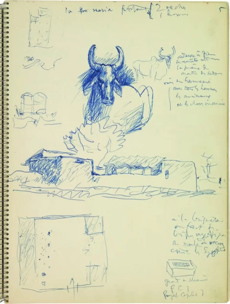
Architects continue to depend heavily on manual sketching, as it allows them to swiftly and unrestrictedly communicate their ideas. The distinctive characteristics of hand-drawn designs can be used to construct digital schematics. Below are 5 of the most famous architects and their concept hand drawing sketches that later on became famous projects.
Le Corbusier
Pioneer of modern architecture Le Corbusier expressed his architectural design and urban planning ideas via hand sketches. His abstract shapes and strong lines, which embodied his creative ideas for cities and buildings, often reflected His pictures revealed the spatial arrangement and utility of his designs.
Frank Lloyd Wright
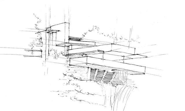
Drawing by hand, Frank Lloyd Wright regularly used flowing lines to show the organic shapes and natural interaction with the nature in his architectural ideas. Fallingwater’s design is a well-known example of this as it emphasizes his idea of organic architecture by showing how perfectly the structure blends with its environment.
Zaha Hadid
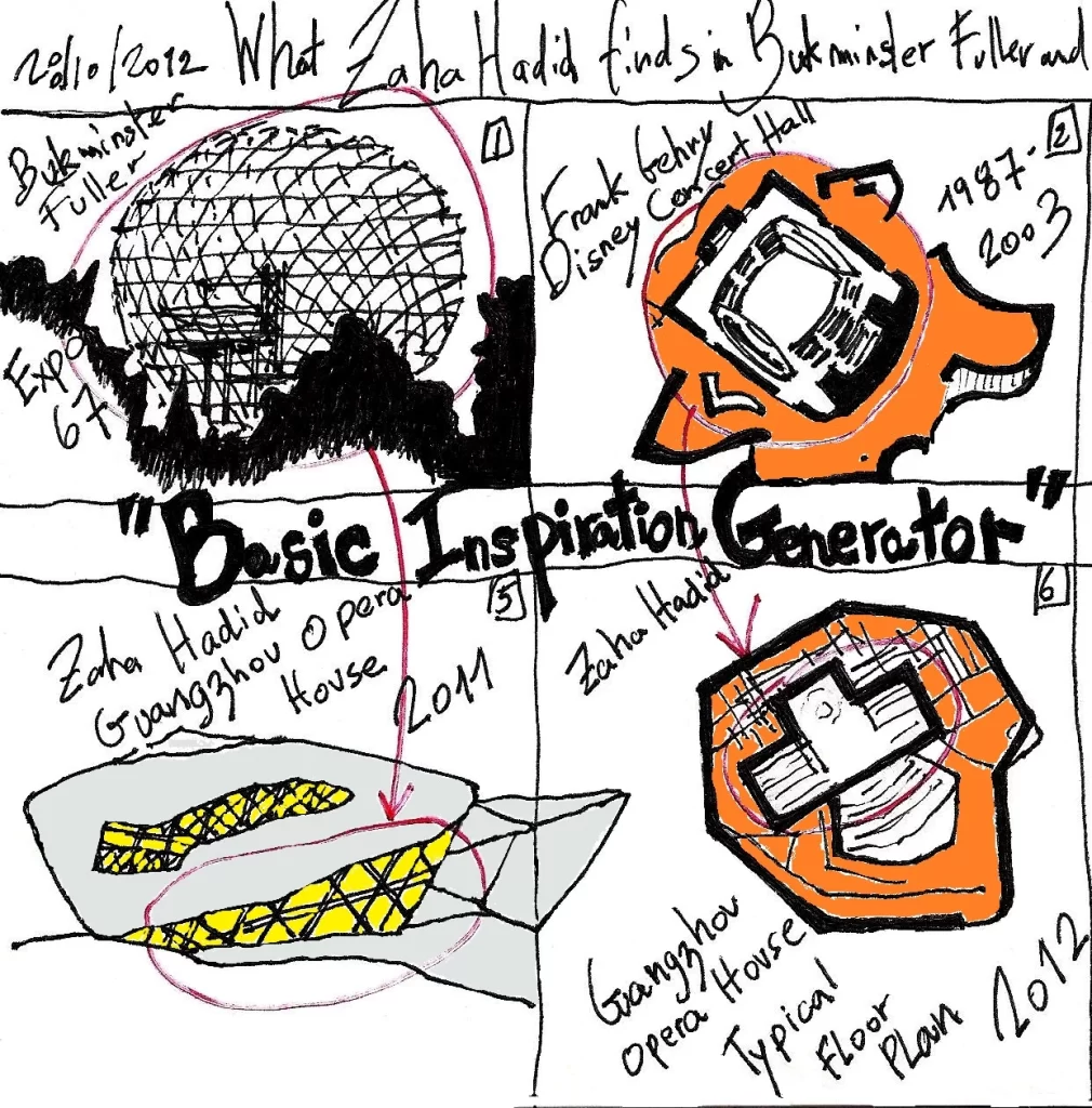
Renowned for her flowing, futuristic designs, Zaha Hadid investigated complex geometries and dynamic shapes using hand sketching. Her sketches for the Guangzhou Opera House show her unique approach to space and form, therefore reflecting the fundamental movement and fluidity of her architectural style.
Renzo Piano
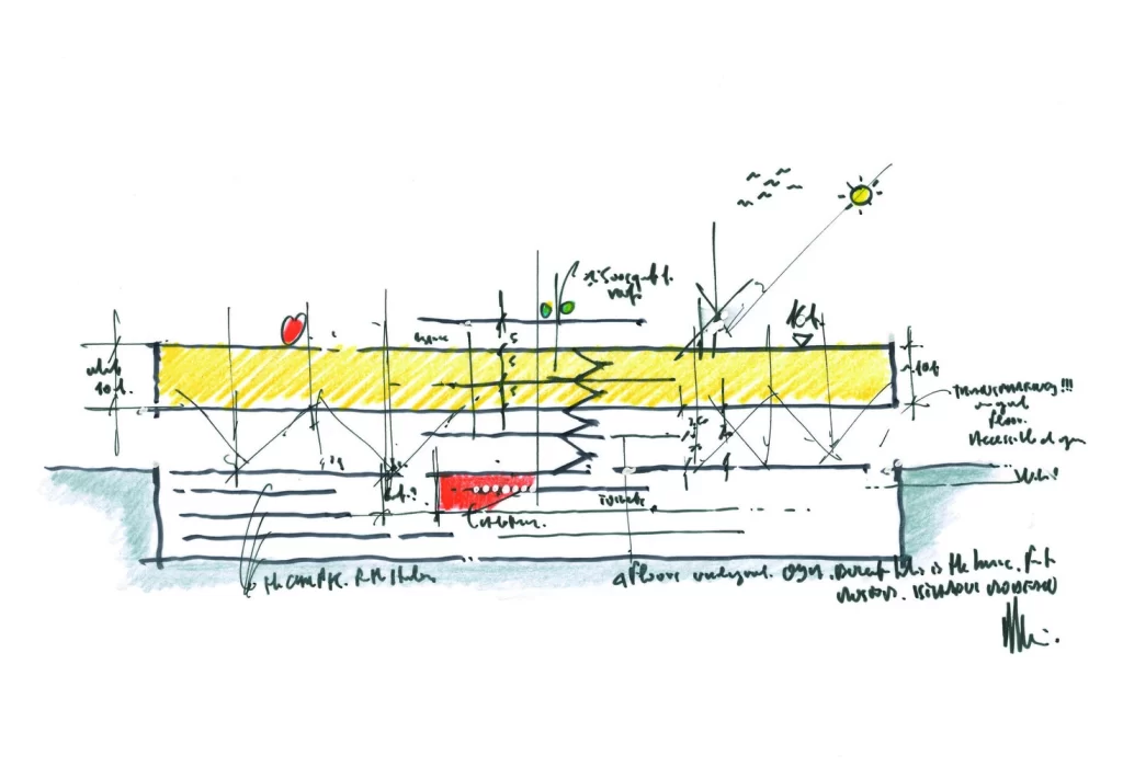
Renzo Piano often uses hand sketches to communicate his design ideas at the conceptual stage. Early designs for the Istanbul modern museum show his creative architectural approach by capturing the building’s features using sections.
2. 3D Modeling Architecture Diagrams
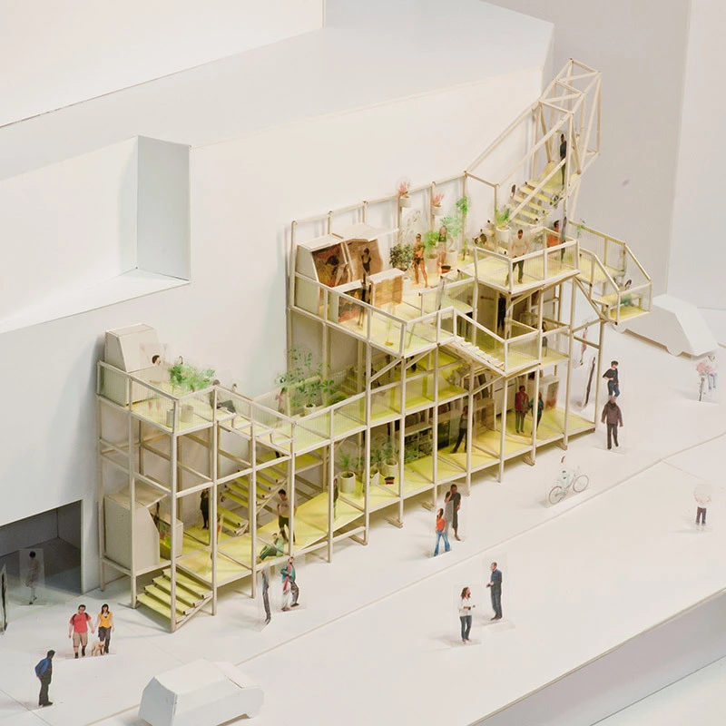
Numerous architects discover that software such as Rhino, SketchUp, Revit, Adobe Photoshop and Illustrator enables them to produce intricate and elaborate designs. These tools are excellent for professional presentations since they improve the visual quality of diagrams in architecture with a focus on massing diagrams. Architects may evaluate various components and implement improvements effortlessly using layered digital software. With the same 3D model, one can generate endless possibilities, styles, outcomes and presentations.
The utilization of online diagramming tools can expedite iterative design processes by facilitating swift layout testing and brainstorming sessions. These platforms facilitate architects in generating fundamental diagrams utilizing pre-designed shapes, hues, and symbols.

3. Both Digital and Hand Sketching
Some architects mix computational and hand-drawn techniques to produce more energetic graphics. Superimposing a computer design on top of a hand-drawn drawing may provide a really unusual and textured effect. Technical knowledge is insufficient to create an attractive architectural sketch.
How to Draw an Architectural Diagram?
First, decide your desired point of view; secondly, compile data to back up it. Before starting to draw the required aspects of the figure, it is advised to list them down. Though it’s simple, the time it takes to use it might not be worth it when compared to a quick sketch that just takes few minutes. If you initially define your objectives, you may save time and effort and develop a better design plan.
Quick sketches help you to arrange your ideas on paper. This will help you to arrange your ideas and start the final design. Use consistent color schemes, fonts, and icons to help the design to unite itself. If you follow one style all through, your designs will be more polished and simpler to understand.
Sort the pieces so that they stand out from the rest of the image and give what is most important top priority. This helps you to ensure that your main point of view is precisely understood. You may enlarge the scale and depth of your model by applying axonometric and planimetric projections among other projection methods. View your designs from several angles to give them complexity. A caption or key that explains the symbols, colors, and other elements helps one to grasp complicated patterns.
A construction sketch should show the purpose of the component pieces rather than pointless information. Exclude everything not absolutely necessary or might compromise your main point of view and pay close attention to detail. Review the plan and make any necessary revisions once you have finished the first draft. Show off your abilities by carefully thinking through the alignment, arrangement, and space.
6 Common Architecture Diagram Examples
Architecture diagramming can be used almost for any architectural drawing. Yet some drawings are more common to be showcased through a diagram than others, for example a construction execution document is better showcased as a technical shop drawing rather than a conceptual diagram, since detail is crucial. Whereas a concept is better perceived using simple low detail diagrams to transform those complicated information into simple ideas for everyone to understand. Below are the most common examples of diagrams in architecture.
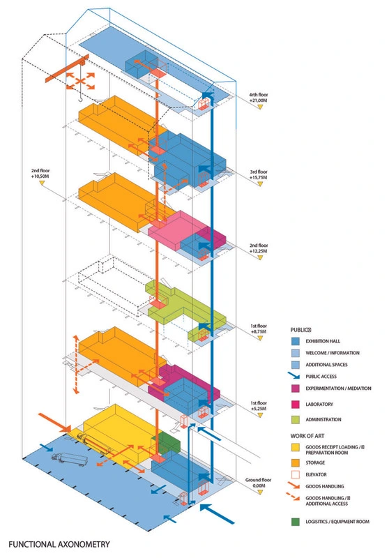
1. Axonometric Drawing
Axonometric drawings maintain size and proportion in all directions by creating a 3D image that is free from perspective distortion. Can be established with a 3D model or just using 2D drawings that gives a 3D illusion.
- Purpose: To get a good sense of the organization in three dimensions.
- Usage: To demonstrate complex spatial relationships and evaluate their level of complexity.
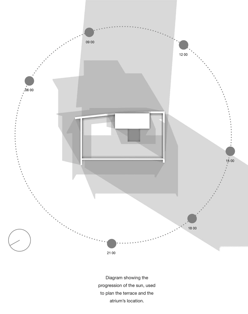
2. Shadow Study
Any time of day or year can be used to observe a building’s shadow in a shadow study. Architectural analysis diagrams, sometimes named shadow analysis, shade analysis or shadow study.
- Purpose: To find out what happens to the building and surrounding buildings when natural daylight strikes.
- Usage: It is essential to develop in a manner that ensures the local community can appreciate the environment and conserves energy.
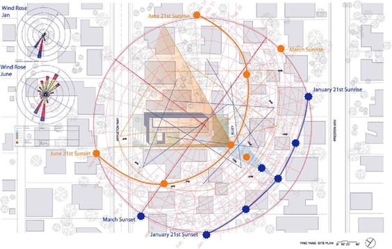
3. Sun Path Diagram
Solar gain and natural light levels may be affected by the way the sun moves over a structure; a sun path diagram can show you how this happens.
- Purpose: Increase HVAC efficiency and make the most of the solar energy available.
- Usage: A great sustainable and passive design strategy to maximizing daylight use.
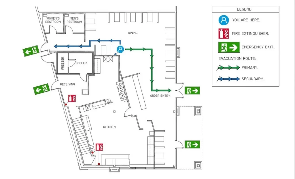
4. Fire Escape Plan
An important part of a fire escape plan is making sure that people can get out of a building safely in case of an emergency. The plan shows the escape routes and safety measures that are in place inside the building.
- Purpose: Safety evacuation.
- Usage: Building codes for compliance with safety regulations.

5. Environmental Impact Diagram
Energy consumption, longevity, and the building’s relationship to the surrounding environment are some of the factors that are considered in an environmental impact diagram.
- Purpose: To showcase low negative impact on the environmental.
- Usage: Important for projects aiming for green building certifications like WELL and LEED.
6. Accessibility Diagrams
A great way to showcase these complicated and detailed blueprints regarding the many accessibility features of a building, such as ramps and elevators, that are necessary to make the building accessible to those who have certain impairments.
- Purpose: Such that, according to the Americans with Disabilities Act, a structure is accessible.
- Usage: Essential for open spaces and compliance with accessibility rules.
Conclusion
Each of these architecture design diagrams provide a unique perspective on a project’s many components. All the way from brainstorming to finalizing a project, they form a solid visual communication system that aids in design.
Planning relies heavily on architectural models because to the special manner in which they blend inspiration and functionality. Improving your style and knowledge of various diagram styles can allow you to express your thoughts more effectively and make a more lasting impact on audiences, partners, and customers. Using these pointers, you can create visuals that do more than just display your ideas; they can also convey compelling stories.

